After defining at least one subject within a project, workflows can be created and executed. While it is possible to integrate existing BrainVoyager files in workflows, the Create Document Workflow is used to create NIfTI files from raw DICOM data files together with JSON and TSV sidecar files. In case NIfTI files are already available, you can also start with the Import NIfTI Document Workflow instead of the workflow described in this topic. While the starting data will be NIfTI files in BIDS folders, subsequent preprocessing workflows produce standard BrainVoyager files (e.g. VMR, FMR-STC, VTC). For future versions it is planned to also save the (pre-)processed data as NIfTI + sidecar files if requested.
In order to define a document creation workflow, the Create Document Workflow icon in the main toolbar of the Data Analysis Manager window can be used. Alternatively the Add button in the Workflows tab can be used after selecting the Create Document entry in the Workflows selection box on the left side of the Add button (s. screenshot below).
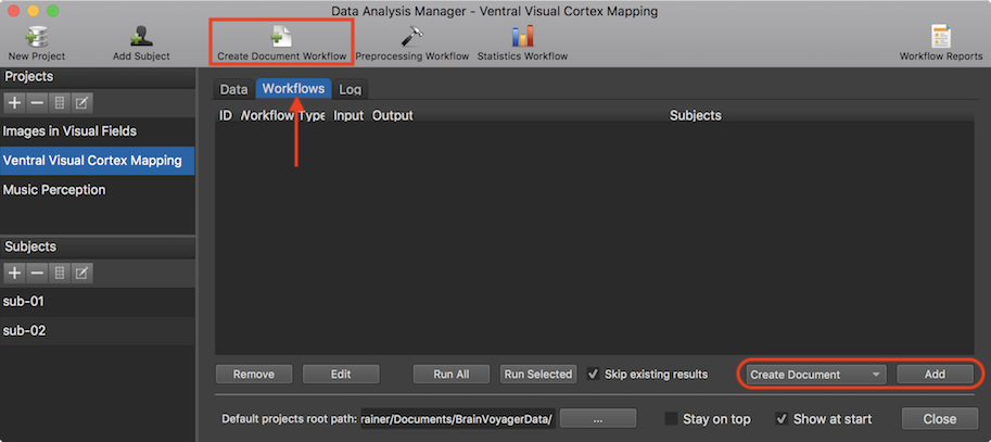
After clicking the Create Document Workflow icon (or the Add button), the Create Document From Scan Data dialog will appear (s. screenshot below). The dialog allows to define a document with the same scan type (e.g. anatomical data set or a functional run) for all available subjects. The desired document type can be specified using the Type selection box (s. arrow below). In the example snapshot below, a "Functional (FMR)" document is selected (default). A name for the document can be provided in the Name text field (s. arrow below, here the name "vislocalizer" (visual localizer) has been entered). In BIDS mode, the name is used for the "task-" field that need to be present in file names of functional data. It is also important to specify to which session a document belongs. If it is not session 1 (default), the In session value box can be used to specify another session number for the document. In case of a functional (FMR) document, also a run number need to be specified (default 1). Note that the session and run numbers should not be used in the name of the document since the program will append the provided session and run numbers automatically to the "base" name given in the Name (task) field.
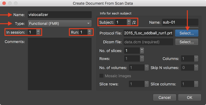
In order to specify the location of the source (DICOM and other) data for the specified scan for each subject of the project, the Subject number spin box is used. The source data as well as an experimental protocol for functional documents should be provided for all subjects browsing through the subjects one by one using the Subject value box in the Info for each subject field. In the snapshot above, the first of two subjects has been chosen and a protocol file has been already specified using the Select button on the right side of the Protocol file text field. The protocol file may be the same for aich subject but usually each subject will have its own run protocol file in order to allow a different order of condition trials or blocks per run and subject. In order to specify the raw DICOM data for the document of the selected subject, the Select button on the right side of the Dicom file text field is used (see screenshot below).
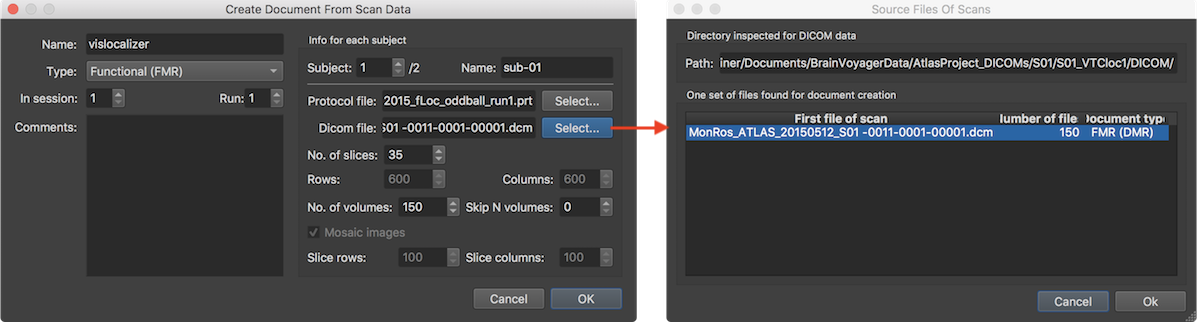
Note that you do not have to select a specific (i.e. first) DICOM file of a series of files in the appearing standard Open File dialog but any file within the folder (even a non-Dicom file) is sufficient since the program will inspect the Dicom files in the selected folder and group the images into data sets automatically. The screenshot above shows the result of the analysis of the selected folder in which the program detected one functional data set consisting of 150 individual image files (corresponding in this example to Siemens mosaic files, each containing all slices of one functional volume). If the folder contains more than one scanning series, multiple entries will appear in this dialog. If the desired data is not represented in the first (automatically selected) entry, select another row in the table. After clicking the Ok button, the Dicom file field in the Create Document From Scan Data dialog will be populated with the name of the first file of the selected data set (shown on the left side above). Furthermore the fields below the Dicom file text field will display information of the selected data set including the number of slices in the No. of slices spin box and the number of rows and columns in the Rows and Columns spin boxes. While it is possible to change some of these entries, one should normally not change them to ensure correct and complete reading of the scanner data. In case of a functional (FMR) or diffusion-weighted (DMR) document, an additional field will be displayed describing the number of volumes in the No of volumes spin box. Furthermore the Skip N Volumes spin box can be used to set a value for skipping some volumes (default value: 0) at the begin of a series, which should only be done in case of functional data containing T1 saturated volumes at the begin. Note also that the protocol file specified for functional runs need to match the data with respect to the number of skipped volumes.
The Mosaic images option is turned on in case of Siemens-specific functional (or diffusion-weighted) DICOM data where the slices of a functional volume are "packed" in a larger image file. In this case the resolution of the embedded slices is displayed in the Slice rows and Slice columns fields while the resolution of the whole image is displayed in the Rows and Columns fields.
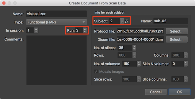
In the screenshot above, the scan information for the selected scan series is shown in the right lower part. Note also that this is the specified source data for run 3 of subject 2 (see red rectangles) of the same "vislocalizer" project as described above, i.e. the functional scanning in this example data set has been spread out over 3 runs of one session for each subject. After having specified the source data of the document for all subjects of the current document, the dialog can be closed by clicking the Ok button.
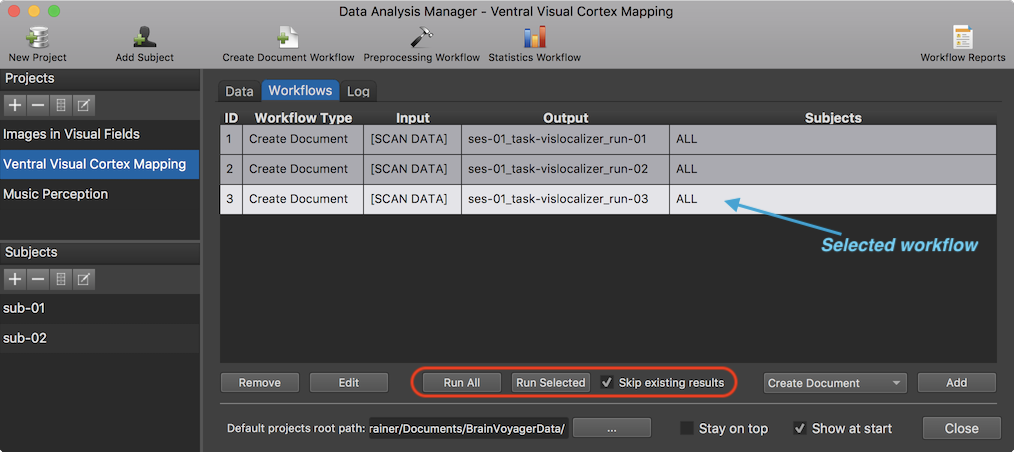
After defining a workflow, it will be added in the Workflows tab. In the screenshot above, three entries are shown representing the 3 defined "Create Document" workflows (one for each functional run) as shown in column Workflow Type. The name "[Scan DATA]" in the Input column indicates that the data uses raw Dicom source files as input. As can be seen in the Output column, the name ("vislocalizer") of the three specified functional runs in the Create Document From Scan Data dialog is appearing in the BIDS required "task-" substring for file names of functional scans. Furthermore, runs are specified in the "run-" substring and sessions with the "ses-" substring. Note that BrainVoyager always uses the "ses-" and "run-" substrings even if BIDS would allow to drop them in case that only one run or session (as in the example case) is available. With these session, run and task identifiers, each workflow output document is uniquely identified. The names displayed in the Output column, will be combined with the subject code (e.g. "sub-01") to produce the file names that will be stored to disk in the subject folders when running the workflows (see below).
In case that more subjects are added to the project at a later stage, no new workflows should be defined; the new subjects should be added to existing workflows by invoking the Create Document From Scan Data dialog for existing workflows. This can be done by clicking the Edit button in the lower part of the Workflows tab after selecting a workflow. A workflow entry can be selected by clicking the entry with the left mouse button or by using the keyboard up/down keys; note that the currently selected workflow is easily recognizable because it is highlighted in the Workflows list (see screenshot above). After clicking the Edit button select the new subject(s) in the Subject number spin box and provide the source data as described above. A selected workflow can also be deleted using the Remove button in the lower part of the Workflows tab, whcih may be useful if one wants to define a workflow from scratch. When clicking the Edit or Remove button, the respective function is applied to the currently selected (highlighgted) workflow entry.
At this stage the workflows are only specified but not yet executed. To run a selected workflow, the Run Selected button is used (see screenshot above). In case you want to execute all defined workflows in the order they are defined, the Run All button can be used. If the Skip existing results option is checked (default), workflows will skip processing data if the expected output files already exist on disk in order to save processing time. If, for example, a new subject is added and the workflow rereun, only the new subject's data would be processed. Note that it is however possible to force recreation of the output data by turning off the Skip existing results option prior to running workflows.
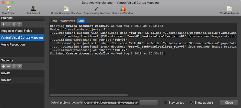
When executing one or more workflows, the data analysis manager switches automatically to the Log tab, which provides information about the progress of the running workflow(s) (see screenshot above). The information in the Log tab is updated incrementally indicating which data set of whcih subject is currently processed and if the respective sub-process completed successfully or if an error has been encountered. Subjects and processed input and outtput data are identified by the respective subject code and generic file names. Sub-processes within loops over subjects and data sets are marked by indentation (4 dots mark one level of indentation). Note that the logged information is also stored to disk so that the process information can be inspected (when reopening BrainVoyager) at a later point.
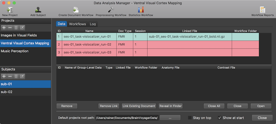
When workflow processing has been completed, the data analysis manager switches from the Log tab to the Data tab presenting the produced workflow output data. Using the tab bar, it is also possible to quickly switch between the Data, Workflows and Log tab at any point. Furthermore, workflow report(s) are created and displayed (see "Workflow Report" section below). In the snapshot above, the output data generated from the first executed workflow is displayed for the selected subject "sub-01". Since the other two workflows have not been executed at this stage, the entries are colored in red indicating missing data.
To inspect the data of any other subject of the current project, select the code name of the subject in the Subjects pane. The data in the Data tab is organized in two tables, the subject-specific data table on top and the group-level data table below (for details about the latter see topic Group-GLM Statistics Workflow). Note that it is possible to temporarily hide the group-level table by grapping the separating horizontal divider with the mouse and moving it all the way down. The Name column in the subject-specific data table shows the generic name that mathces the name created and displayed in the Output column of the respective entry of the Workflows list. The Doc Type column shows the type of the generated document (here "FMR"). The Session column shows the session number to which the respective document has been assigned. While the Name column shows the generic name of a created document (independent from the currently selected subject), the Linked File column contains the actual name of the file stored to disk; the name on disk starts with a prefix identifying the subject (e.g. "sub-01_" in the screenshot above). Since the document creation workflow was run in BIDS mode, the generated file is NIfTI file containing the subject, session and run identifier as well as the "_bold" string identifying it as containing the data of a functional scan. If this linked file is not available in the expected folder (e.g. before running the workflow or when an error prevented creation of the file), the respective row in the data table will be displayed in red color as demonstrated in the two other entries. If the linked file is available on disk, the data table entry will be displayed in green color.
The Workflow Folder column contains the name of the created folder containing the resulting files and is itself stored under the "derivatives" folder. Note, however, that the resulting documents (NIfTI) files generated from raw scanner data are not stored in a workflow folder but directly under the project folder as specified by BIDS. While usually not relevant to understand the processing of the Data Analysis Manger, it might be helpful to inspect the data organization on disk. In order to show the data of the top-level project folder, one can click the Reveal Project Folder in Finder (macOS) or Reveal Project Folder in Explorer (Windows) icon in the toolbar of the Projects pane. The screenshot below shows the state of the project data folder "Ventral_Visual_Cortex_Mapping" right after executing the first Create Document workflow.
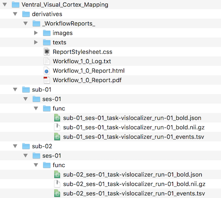
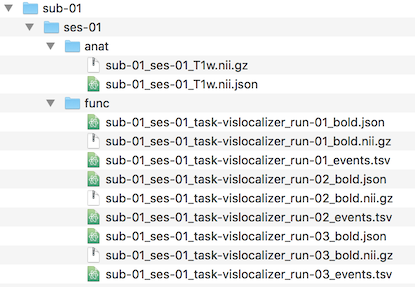
The document creation workflow results are stored in the subject folders ("sub-01" and "sub-02" in this example case). Since the generated NIfTI files represent functional scans, they are stored under the "func" folder for each subject as required by BIDS. The func folders are themselves sub-folders of the session ("ses-01") folder (BIDS specifies this as optional in case that only one session is used). Note that next to the (compressed) NIfTI files the "func" folders also contain a sidecar .json file and a sidecar .tsv file as required by BIDS (for details see topic NIfTI with JSON and TSV Sidecars). If the workflow would not have been run in BIDS mode (deprecated), the created functional data folders would contian BrainVoyager FMR and STC files together together with all relevant associated data including the protocol (.prt) file that has been provided when defining the source data.
The screenshot above also shows the "_WorkflowReports_" folder under the "derivatives" folder, which stores log and report data for all executed workflows. It contains three major types of data: the information logged and visualized in the Log tab during processing ("Workflow_[ID]_Log.txt"), created workflow reports as HTML files ("Workflow_[ID]_Report.html") and as PDF files ("Workflow_[ID]_Report.pdf"). Note that the HTML files access images and text files that are been stored in the sub-folders iImages" and "texts" respectively.
In case that output data of executed workflows has not been created, i.e. if colored red (for one or more subjects) in the Data tab although the workflow has been executed, inspecting the logged information in the Log tab may be helpful to identify a potential issue. In order to see the log information of the intended workflow, the respective workflow must be selected first in the Workflow tab before switching to the Log tab. After fixing a problem (the reason could e.g. be that source data might not have been found), the corresponding workflow can be selected and restarted in the Workflows tab. In case that the missing data is created without the Data Analysis Manager, the BrainVoyager database should be updated by linking the file on disk to the subject's document entry using the Link Existing Document button in the Data tab. If that button is clicked, a dialog will show all files of the type of the expected document within the appropriate subject data folder. Note that the document data need to be created in (or copied to) the appropriate folder within the project's folder tree before linking it to the document entry. To show the data folder of a specific subject, the Reveal Subject Folder in Explorer (Windows) or Reveal Subject Folder in Finder (macOS) icon in the Subjects pane can be clicked. Within the displayed folder the appropriate session and data type folder can be selected. In case that a subject's file on disk is properly linked (green table entry), the Reveal in Explorer (Windows) or Reveal in Finder (macOS) button in the Data tab can be used to open the containing folder on disk with the document file selected. While usually not necessary, the link to a file on disk can also be removed intentionally by using the Remove Link button after selecting the respective entry in the Data table.
The Data tab can also be used to open created documents simply by clicking the Open button after selecting an entry in the data table of the currently selected subject. More conveniently, the document can also be opened simply by double-clicing its entry. The opened document will appear in BrainVoyager's multi-document area in the same way as if it would have been opened using the standard Open File dialog or when clicking a document in the Recent Files pane. The document of a selected data table entry (if open) can also be closed from the Data tab by clicking the Close button. In case one wants to clear the multi-document area, e.g. when many documents (from multiple subjects) have been opened, the Close All button can be used.
The basic functionality of the Create Document workflow has been described above for functional (FMR) scans (runs). The workflow can be used to create all other basic BrainVoyager document types including 3D anatomical (VMR) documents, 2D (multi-slice) anatomical (AMR) documents and diffusion-weighted (DMR) documents. The screenshot below shows how a workflow for creating 3D anatomical (VMR) documents is specified for the two subjects of the example data set using the Create Document From Scan Data dialog.
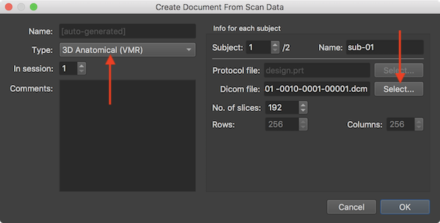
Some dialog elements are adjusted after selecting the "3D Anatomical (VMR)" document in the Type selection box; the Name text field, for example, can not be filled in BIDS mode since the file name will be auto-generated (as stated in the text field) with the standard name for 3D data files (see below). The Run value box is also not shown and the Select button next to the Protocol file field is disabled since protocols are only needed for functional documents. The detected information about the selected DICOM data is also simpler than in case of functional (mosaic) data only containing the detected number of slices in the No. of slices spin box and the dimensions of individual slices in the (non-editable) Rows and Columns fields. Note that the DICOM data should be specified for each subject using the Subject spin box and the Select button on the right side of the Dicom file field.
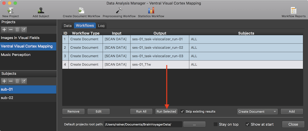
The screenshot above shows the added workflow (entry 4) after clicking the OK button in the Create Document From Scan Data dialog. To run the workflow, the Run Selected button can be used. Note that one could define all four workflows before running them using the Run All button. This would separate the workflow "setup" time from the workflow execution time. The snapshot below shows the resulting entry in the subject-specific data table of the Data tab for subject "sub-01" and a section of the generated workflow report on the right side.
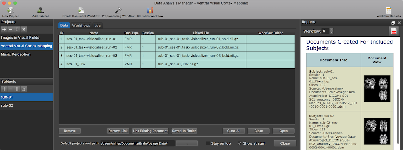
The screenshot below shows the generated functional and anatomical documents created for subject 1 after running all 4 workflows. The "func" folder now shows the data for all 3 runs and the "anat" folder contains the NIfTI file and sidecar JSON file for the 3D anatomical (VMR) data. Besides placing the data in the "anat" folder, the auto-generated file name contains the "T1w" string indicating that this data is from a T1 weighted MRI pulse sequence.
After having created raw documents for the subjects of a project, one can inspect the generated workflow reports and define preprocessing workflows.