Turbo-BrainVoyager v4.4
Conditions and Regions
The Paradigm tab of the Data Simulator dialog allows to specify a design and brain regions in MNI space. Simulated activation effects can be specified for each condition of the design and each included brain region. For simulations of pattern activation, activation effects can also be set at the level of individual voxels.
Providing a Protocol
The experimental design needs to be defined as a standard (Turbo-)BrainVoyager protocol (PRT) file, which can itself be defined using the Protocol dialog, or generated directly as a text file. A created PRT text file can be selected using the Browse Protocol ('...') button on the right side of the Protocol text field.
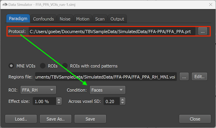
In the example shown above, the 'FFA_PPA.prt' protocol has been selected using the Browse Protocol button and its file path is shown in the Protocol text field. All conditions defined in the PRT file ('Faces' and 'Houses' in the example PRT file) are made available in the Condition selection box in the lower section of the dialog (see arrow in screenshot above). Each condition specified in the protocol can be selected to define activation effects for specified brain regions. When datasets are generated, a standard two-gamma function is used to create simulated BOLD time courses for the intervals defining each condition in the provided protocol. The sections below describe how different amplitude (effect sizes) of the simulated condition activation effects can be specified for targeted brain regions.
Providing Brain Regions
There are 3 different ways to define regions in the brain for which activation effects can be defined: VOIs in MNI space and ROIs in slice space for regional activation effects, and ROIs with condition patterns for voxel-level pattern activation effects.
Specifying Regions as VOIs or ROIs
In case one wants to simulate an activation effect for a specific brain area (but not at the level of individual voxels), the MNI VOIs approach can be selected (see below). In this case a volumes-of-interest (VOI) file in MNI space must be provided using the Browse Region ('...') button on the right side of the Regions file text field (see red rectangle below).
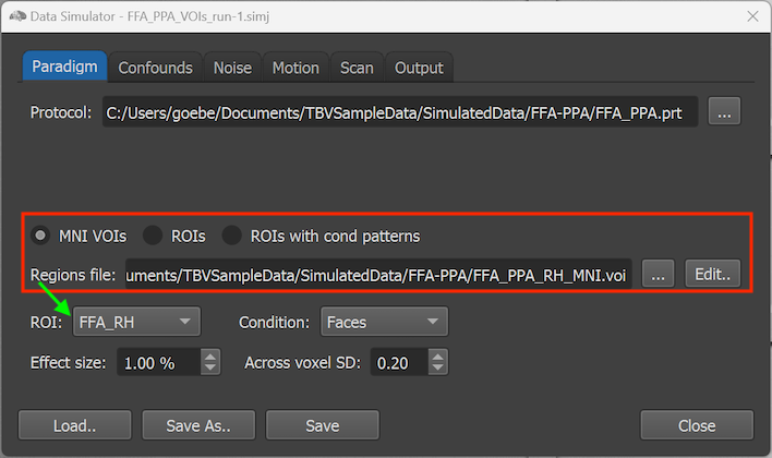
The names of the regions (VOIs) defined in the .VOI file are made available in the ROI selection box (see green arrow above). In the example above, the FFA_PPA_RH_MNI.voi file contains only two regions (FFA_RH and PPA_RH) that are selectable in the ROI box.
Regions can also be defined using an ROI file by selecting the ROIs option (see upper row in red rectangle in screenshot above). With this selection, the Browse Region ('...') button on the right side of the Regions file text field can be used to select a prepared '.roi' file. This can be useful, for example, to re-use a .ROI file saved during a previous simulation, or when a precise selection of voxels is needed.
The ROIs with cond patterns option makes it possible to simulate pattern activation effects, which is useful to test pattern classification experiments and (semantic) neurofeedback studies. With this selection, the Browse Region ('...') button on the right side of the Regions file text field can be used to select an existing '.rcps' file. An .RCPS file is similar as a standard .ROI file but it contains activation effects for each ROI voxel and condition. To get an initial RCPS file, it is best to run a simulation with regions defined via a standard ROI (or VOI) file. At the end of running the created simulation data, an RCPS file will be saved automatically with voxel values reflecting estimated condition beta values. It is also possible to select one or more ROIs at the end of real-time analysis of simulated data manually and to then save the selected regions with current beta values to disk as an RCPS file by using the Save RCPS File item in the Analysis menu. You can also inspect the voxel-level pattern contents by using the Show ROI Condition Patterns (RCPS) item in the Analysis menu, which will show the Edit ROI Conditon Patterns dialog that will be described in detail below in section 'Specifying Pattern Activation Effects'.
Specifying Activation Effects for Regions and Conditions
When selecting the MNI VOI or ROI option, activation effects for all possible combinations of regions and conditions can be specified using the ROI and Condition boxes. In the example case, activation effects for 4 combinations - 2 VOIs x 2 conditions - can be specified. The effect size per region x condition combination is specified in the Effect size number field as a percent signal change (PSC). As default, all conditions are set to an activation effect of 1% relative to baseline activity in all regions. To specify more interesting activation effects, change the value in the Effect size number field by either typing in a new value or by using the spin box on the right side of the field, which will increase or decrease the value in steps of 0.1 PSC. For the example case, the following values have been entered:
| VOI/Cond | Faces | Houses |
|---|---|---|
| FFA_RH | 1.4 | 0.1 |
| PPA_RH | 0.3 | 1.2 |
With these values we simulate that region FFA (here only in the right hemisphere) responds strongly to face stimuli (1.4) but only weakly to house stimuli (0.1) whereas PPA shows the opposite pattern, i.e. it responds modestly to faces (0.3) but stronlgy to house stimuli (1.2). After entering these values using the e ROI and Condition boxes, it is advised to save the information to disk using the Save (or Save As) button.
The specified effect size per condition is used for each voxel of the respective VOI. To simulate more realistic data, the 'true' activation values per voxel can be modulated by a random component which is specified with the Across voxel SD number field (default value: 0.2). If this value is set to 0.0, each voxel in the respective VOI will receive precisely the effect size PSC value specified. If this value is larger than 0.0, a random effect size is added on top of the specified value for each voxel drawn from a Gaussian distribution with mean 0.0 and a standard deviation (SD) obtained from the Across voxel SD number field. This creates different 'beta' values for each voxel in the voxels of a VOI when generating the simulation data although only one effect size value is defined per VOI and condition.
Specifying Pattern Activation Effects
When one selects the ROIs with cond patterns option, activation effects are defined at the level of individual voxels and the ROI and Condition boxes used for the MNI VOI and ROI options are, thus, disabled (see screenshot below).
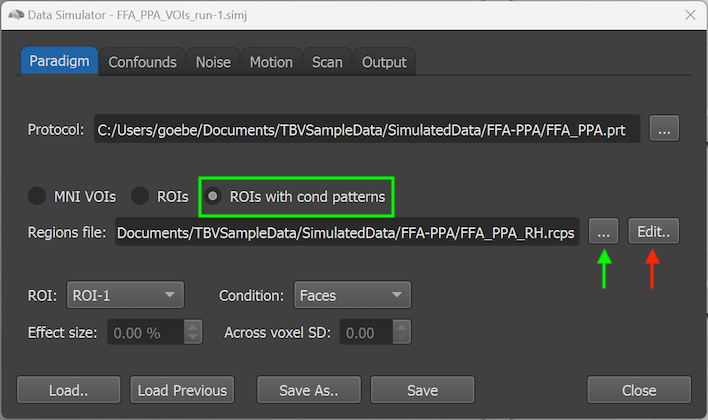
To define patterns at individual voxel level, the Edit button on the right side of the Regions file text field (see red arrow in the screenshot above) can be clicked after selecting an initial RCPS file that can be obtained as described above. After clicking the Edit button, the Edit ROI Condition Patterns dialog will be shown (see screenshot below).
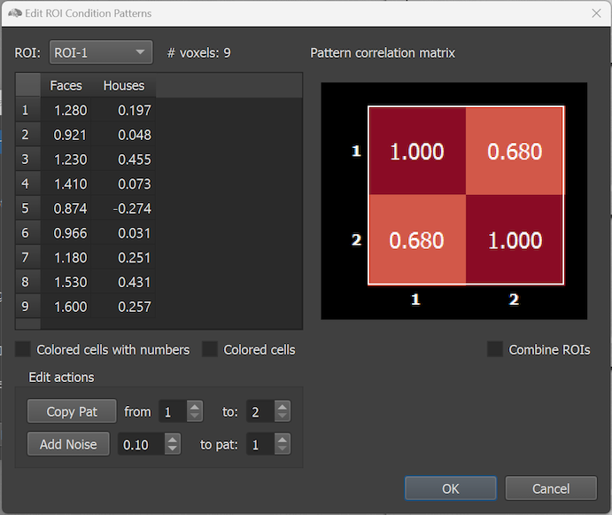
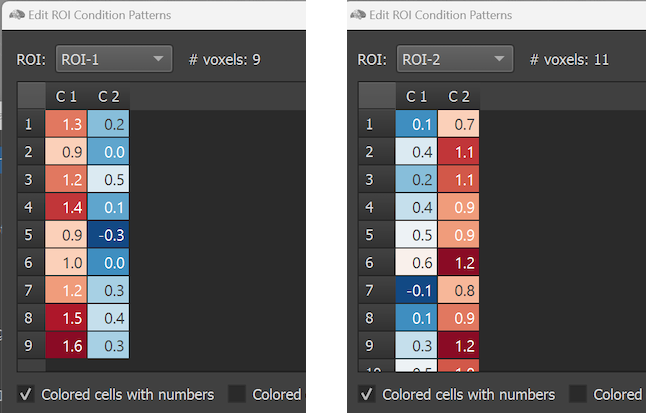
The dialog shows on the left side the simulated effect sizes of the voxels of an ROI that can be selected in the ROI selection box. The right side of the dialog shows the pattern correlation matrix indicating the similarities between condition patterns. In the example only two conditions are modelled and, thus, the pattern similarity matrix has only two rows and columns. Note that the ROIs in the selection box have generic names (ROI-1 and ROI-2) but they do correspond to the FFA and PPA regions in the right hemisphere. Since the regions were, however, manually selected in the Multi-Slice view, they were not automatically provided with proper names when the RCPS file was saved manually (see below how to change the names of the ROIs). The # voxels field shows the number of voxels in the selected ROI ('9' for the selected ROI with the name 'ROI-1' in the screenshot above). The Voxel Effects table below the ROI selection box shows effect values (usually interpreted as beta values) for each voxel of the selected ROI. Each column corresponds to a condition of the modelled paradigm. The effect values in the table can be simply edited by selecting a cell and by then typing a desired value. To save the edited values to disk, the OK button can be used. The size of the effect values can be visualized (additionally or exclusively) using a blue-to-red color bar by selecting the Colored cells with numbers or Colored cells option. The screenshot below shows the cells after selecting the former option for the two ROIs. To keep columns in one of the coloring modes of equal width, the condition names are abbreviated by the strings 'C1', 'C2' and so on.
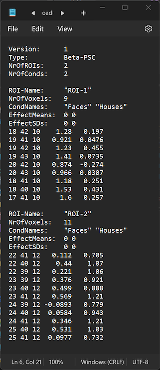
Note that it is possible to open and edit an RCPS file also in a standard text editor. The RCPS file loaded above in the Edit ROI Condition Patterns dialog is, for example, shown in the Windows Notepad application in the screenshot below. Working directly with the RCPS text file can be useful, for example, to change names of ROIs, which is not (yet) possible in the Edit ROI Condition Patterns dialog. One can also remove (or add) voxels per ROI, for example, to have a precise number of voxels, but one needs to ensure that the number in the NrOfVoxels: entry matches the number of voxels (rows) entered in the respective section of the modified ROI.
The screenshot below shows the reopened Edit ROI Condition Patterns dialog after selecting an updated RCPS file in which the ROI names 'ROI-1' and 'ROI-2' have been changed in a text editor to the semantically more meaningful names 'FFA' and 'PPA'. The screenshot below also shows the Colored cells option that does not show the number values.
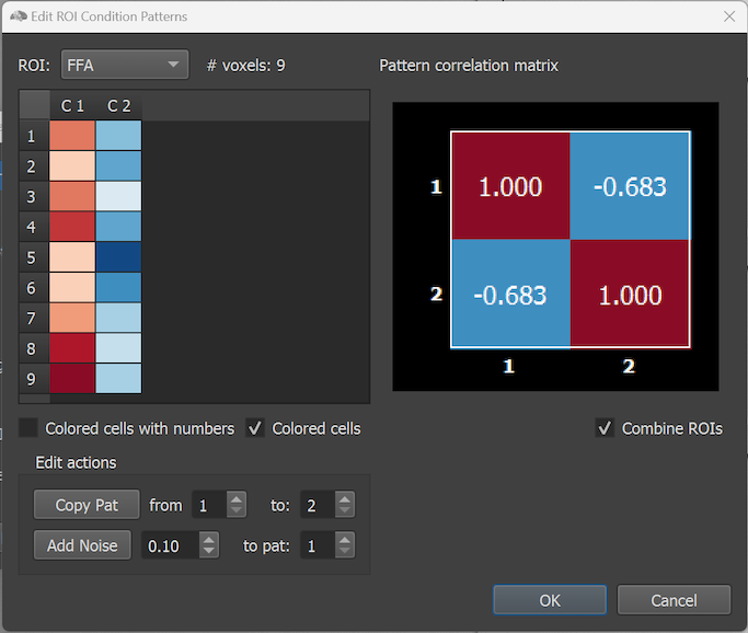
In the screenshot above the Combine ROIs option has been turned on, which combines the effect values of the modelled conditions across all available ROIs (here two). As can be seen in comparison to the single-ROI similarity matrices above, the combined similarity matrix shows a strong negative correlation between the two patterns reflecting that opposing responses in the 'FFA' and 'PPA' region.
Copyright © 2002 - 2024 Rainer Goebel. All rights reserved.