Turbo-BrainVoyager v4.4
The Contrasts Window
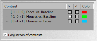
The Contrasts Window shows a list of all defined contrasts. Contrasts are typically defined automatically but can be also defined explicitly using a Contrast Definition file. The Contrast column lists the names of available contrasts. A contrast can be enabled by clicking in the ">"or "<" column of the respective contrast. Squares with a cross in these columns indicate that the contrast is enabled while empty squares indicate that the contrast is disabled. These squares act as toggles, i.e. they can be clicked repeatedly to flip between the enabled and disabled state. Contrasts are enabled either one-sided or two-sided. If, for example, the ">" but not the "<" state of the "Houses vs. Faces" contrast is turned on (contrast names are from the example above), only the voxels exhibiting significantly more activity during the "Faces" condition than the "Houses" condition will be shown ("Houses > Faces"). If on the other hand the"<" state but not the ">" state is enabled, voxels will be shown exhibiting significantly more activity during the "Faces" condition than during the "Houses" condition ("Houses < Faces"). If both are turned on, the contrast is enabled in a two-sided way ("Houses unequal Faces"). The resulting statistical map of each enabled contrast is superimposed on the images shown in the various brain views. It is also possible to specify a conjunction of contrasts by turning on the Conjunction of contrasts option. If this option is checked, the minimum of t values of all active contrasts for a voxel is determined and used as the voxel's threshold for the resulting conjunction map. Note that all included contrasts should be of the same direction (i.e. all ">" or all "<") when using a conjunction.
If a defined contrast is enabled, all voxels passing the current significance criteria (t threshold) are shown in the Contrasts Overlay Window. If the Colors Code Contrasts mode is selected (see Keyboard and Mouse Functions), the significant voxels belonging to a particular contrast are color-coded in the respective contrast color. The contrast color is shown in the Color column on the right side of each contrast and correspond to the color of the respective protocol condition for basic contrasts (e.g., "Faces vs. Baseline").The color of a contrast may be changed by double-clicking on the contrast color square. This is allowed, however, only after real-time analysis has been completed. The colors of the basic contrasts correspond to the colors of the main protocol conditions if automatic contrast creation is turned on (default). In order to fully control the definition of contrasts including their names and colors, a Contrast Definition file may be specified.
Automatic Creation of Contrasts
There are two levels, "1" and "2" for the automatic creation of contrasts. The level can be defined in the AutoContrastGenerationLevel spin box in the Statistics tab of the TBV Settings Dialog. Furthermore, the ContrastFile field must be empty, otherwise the contrasts specified in that file are used.
If level 1 is specified, contrasts are defined testing each main condition against baseline. It is assumed that the first condition of the protocol corresponds to the baseline (or "Rest" or "Fixation") condition. In the example above, three conditions were defined in the protocol, "Baseline", "Faces" and "Houses". The program thus creates two contrasts testing the two main conditions against base line ("Faces vs. Baseline" and "Houses vs. Baseline"). In the actual design matrix created automatically, the first condition (baseline) is not explicitly modeled although shown in the contrast names. The design matrix contains, however, the constant term confound predictor, which models the baseline signal level. In summary, the contrasts of level 1 test for the significance of explicitly modeled individual main conditions against baseline (test of individual beta values for main conditions). A level 1 contrast shown as [-1 +1 0] is actually tested as [+1 0] in the underlying GLM when showing only the predictors of interest or [+1 0 0] when adding the confound constant predictor at the third position. The colors of the contrasts are set to be identical to the colors of the respectively tested main condition from the protocol definition.
If level 2 is specified (default), all predictors of level 1 are first defined. In addition, contrasts for comparing all pairs between all main conditions are defined. In the "Baseline", "Faces", "Houses" example, only one pair needs to be constructed comparing "Houses" vs "Faces" (see contrast 3 in the example snapshot above). If there would be three main conditions, three contrasts would be defined ("c2 vs c1", "c3 vs c1" and "c3 vs. c2") together with three level 1 contrasts. The colors for these contrasts are calculated by adding the RGB color definitions of the individual conditions. In order to specify other contrasts, a Contrast Definition File must be provided.
Copyright © 2002 - 2024 Rainer Goebel. All rights reserved.