BrainVoyager v23.0
Functional Preprocessing Workflow
The functional preprocessing workflow can be used to perform a series of preprocessing options for each subject, session and run of a project. The available routines and parameter settings for this workflow are largely identical to those of the conventional single-document FMR preprocessing options as described in the Preprocessing chapter.
Creating and Connecting the Workflow
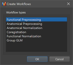
The functional preprocessing workflow can be created using the Create Workflows dialog that can be launched by using the Create button in the Workflows tab of the Data Analysis Manager window. In the appearing dialog, the Functional Preprocessing entry needs to be selected (see screenshot below). After clicking the OK button, the new workflow appears in the Workflows tab (see figure below). The ID column indicates that the unique identifier '3' has been assigned to this workflow; the column Type shows the generic name "Functional Preprocessing" for the assigned (and stored) type ID (1); the column Name shows the default name "func-preprocessing" that has been assigned to this workflow, which can be changed in the Workflow dialog (see below).
The empty cells in the Input and Output columns of the new entry in the Workflows table indicate that the instantiated functional preprocessing workflow is not yet ready to be executed since no data connections have been made. To connect the workflow to input data, the Connect Workflows dialog is used, which can be invoked by clicking the Connect button in the Workflows tab.
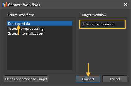
The Connect Workflows dialog shows in the Source Workflows list on the left side all available data sources.. A specific workflow is identified by its unique ID and its name ("[workflow-ID]: [workflow-name]"). On the right side the Target Workflow is displayed to which data can be connected which is the selected functional preprocessing workflow. Since no workflow has been defined for functional data yet, only the original NIfTI source data ("0: sourcedata" entry) can be selected as input for the functional preprocessing (target) workflow. Note that no specific dataset (file name) needs to be specified since the program uses the predictable BIDS directory tree to find the functional NIfTI source files (per session) in the respective "func" folder(s) of each subject.
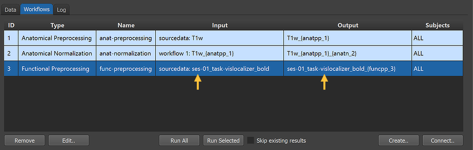
After clicking the Connect button in the Connect Workflows dialog, the established connection is made and the workflow entry is updated accordingly. The arrows in the figure above indicate that the functional preprocessing workflow will use the original NIfTI data in the sourcedata folder as input using the "ses-01_task-vislocalizer_bold" file as input. The program has retrieved this name by checking the full NIfTI file name ('sub-01_ses-01_task-vislocalizer_run-01_bold.nii.gz') in the sourcedata folder of subject 1 (usually 'sub-01') as a proxy for all subjects and removed the subject and run IDs (as well as the file extension) since the workflow will process (if not restricted) the data from all subjects and all runs of the same session. In case of multipe sessions, multiple input-output specifications would be generated, one for each session. The reason for this is that it helps to coregister functional data with the same-session anatomies when running the Coregistration workflow.
Inspecting and Editing Workflow Settings
In order to inspect and eventually change settings, such as parameters that control the processing, one can invoke the Workflow dialog by double-clicking the workflow entry or by clicking the Edit button (see arrow above).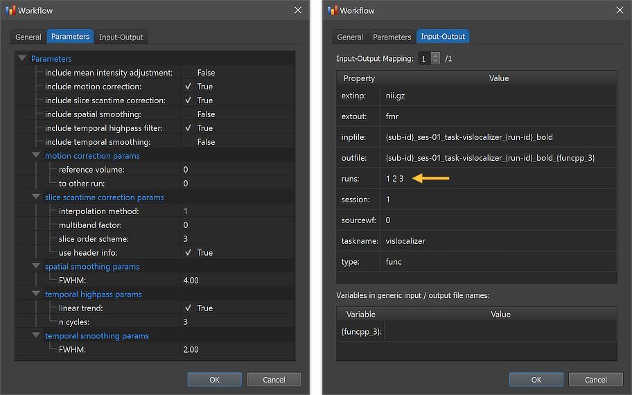
The figure above shows the contents of the Parameters tab (left) and he Input-Output tab (right) of the Workflow dialog. The Parameters tab shows the parameters specific for the selected workflow, which can be inspected as well as changed. The first set of parameters of the functional preprocessing workflow specify whether a certain operation will be included or not; as default, motion correction, slice scan time correction and high-pass filtering will be performed, while mean intensity adjustment, spatial and temporal smoothing will not. This can be changed by checking or unchecking the "include" options. For most preprocessing operations, additional settings are available that can be changed before starting the workflow.
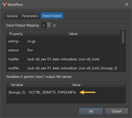
The right side of the figure above shows the Input-Output tab, which displays information related to the established data flow connection(s). Each connection (if more than 1) can be viewed by changing the Input-Output Mapping number. The details of the displayed fields are usually not important but it might sometimes be instructive to inspect these (read-only) fields. Probably most relevant are the inpfile and outfile fields, which show the generic functional file name that will be processed with the subject and run substrings replaced by loop variables (enclosed by curly braces '{}'). Note that compared to anatomical files, there are usually multiple runs of functional data within a session. The program has detected 3 run numbers (see arrow) and will use those as values for the "id' section of the loop variable '{run_id}'. The outfile entry extends the input file name with the substring "_{funcpp_3}"; the "{funcpp_3}" part is a processing variable, which is also shown in the Variables in generic input / output file names field (here loop variables, such as subject and run variables are not shown). When running the workflow, processing variables will be replaced with concrete values (substrings) that depend on the included processing steps and parameter settings. When inspecting the variables section in the dialog after running the workflow, concrete values will be displayed. Note that variables (and their values if available) will be handed over to any subsequent workflow so that file names with additional substrings can be constructed before any workflow has been executed.

A global overview of the established connection is graphically displayed when clicking the Data Flow button in the main toolbar of the Data Analysis Manager (see screenshot above). In the appearing visualization the "func-preprocessing" workflow is placed under the "func-sourcedata" node and an arrow connects the functional source data as input with the preprocessing workflow.
Running the Workflow
After selecting the workflow in the Workflows tab (single-click on its row in the table), the prepared functional workflow can be executed using the Run Selected button (or the Run All) button). In case that the Skip existing results option has been turned on (default: off), the program will not process datasets in case that the expected output data are already available. This option is useful (saving time) in case that one adds more subjects to a project and wants to preprocess only the newly added ones. An alternative way to restrict the workflow to specific subjects is to select the desired subset of subjects in the Subjects field in the General tab of the Workflow dialog.
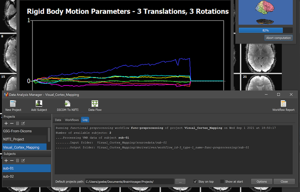
When running a workflow, the program displays the progress of data processing in the Log tab of the Data Analysis Manager window. The screenshot above captures a moment during functional preprocessing (motion correction step for subject 'sub-01').
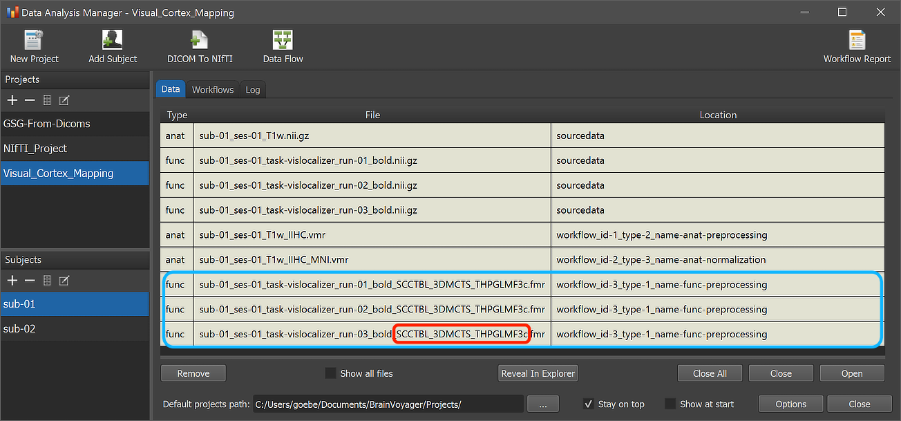
After the workflow has finished processing, the main produced data files can be inspected by switching to the Data tab of the Data Analysis Manager. The blue rectangle in the screenshot above highlights the newly added entries for the selected subject but the same output will be available for all subjects (here only 2) in case that processing was successful. The red rectangle highlights that the produced output file names in the File column now have the additional substring "__SCCTBL_3DMCTS_THPGLMF3c" as compared to the input file names. This substring is also stored now as the value of the "{funcpp_3}" variable as shown in the Workflow dialog (see screenshot below).
The Location column of the Data table of the Data Analysis Manager indicates that the produced files are stored inside the created workflow directoy (under the derivatives folder of the project); the name of the workflow folder 'workflow_id-3_type-1_name-func-preprocessing' contains the unique workflow ID ('3'), its type ('1') and its name ('func-preprocessing'). Note that you can open the produced files simpy by double-clicking the respective rows in the Subject Data table or by clicking the Open button below the table after selecting the respective row in the table. The location on disk of a selected file can be shown in the Finder (macOS) or Explorer (Windows) by clicking the Reveal in Finder or Reveal in Explorer button. The figure below shows the generated directory tree of the workflow on disk fully expanded for subject 'sub-01'.
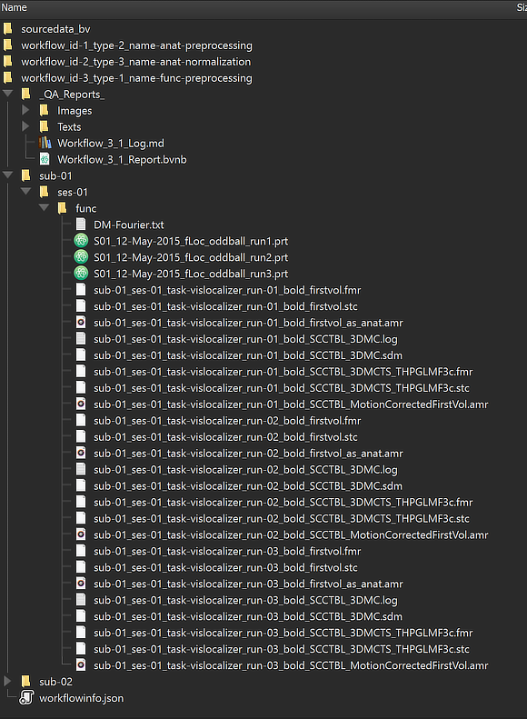
This view illustrates that a workflow on disk replicates the BIDS directory tree for the relevant data (here "func" folders). Besides the main (.FMR header) files shown in the Data table, this view shows that there are many additional files related to each run of the functional data, including the actual 4D data (.STC files), protocols (.PRT files), motion correction parameters (.SDM files) and more. Besides the BIDS sub-directories for each subject, the "_QA_Reports_" folder is also stored inside the workflow directory containing the full log (Markdown) text file and the quality report as a BrainVoyager notebook (see below), which will be shown automatically when the workflow has completed. The workflow report can also be shown at a later time by clicking the Workflow Report icon in the main toolbar of the Data Analysis Manager after selecting the respective entry in the Workflows table.
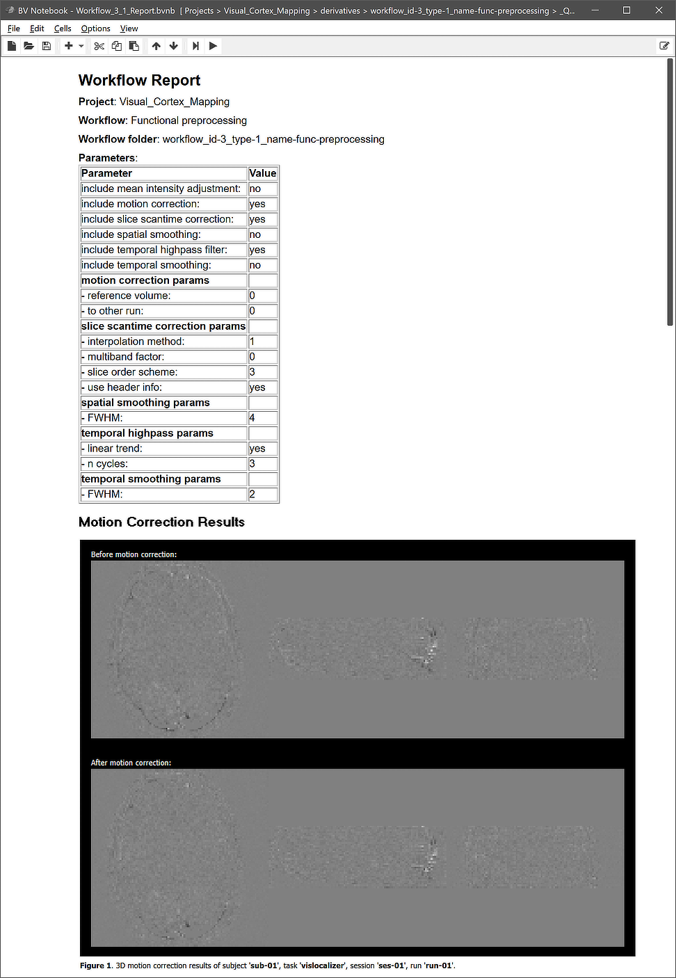
Note that the figures generated per subject contain animations (not visible in screenshot above), for example to show the effect of motion correction. The animation embedded in the quality report for motion correction of run 'run-03' of subject 'sub-02' is shown below.
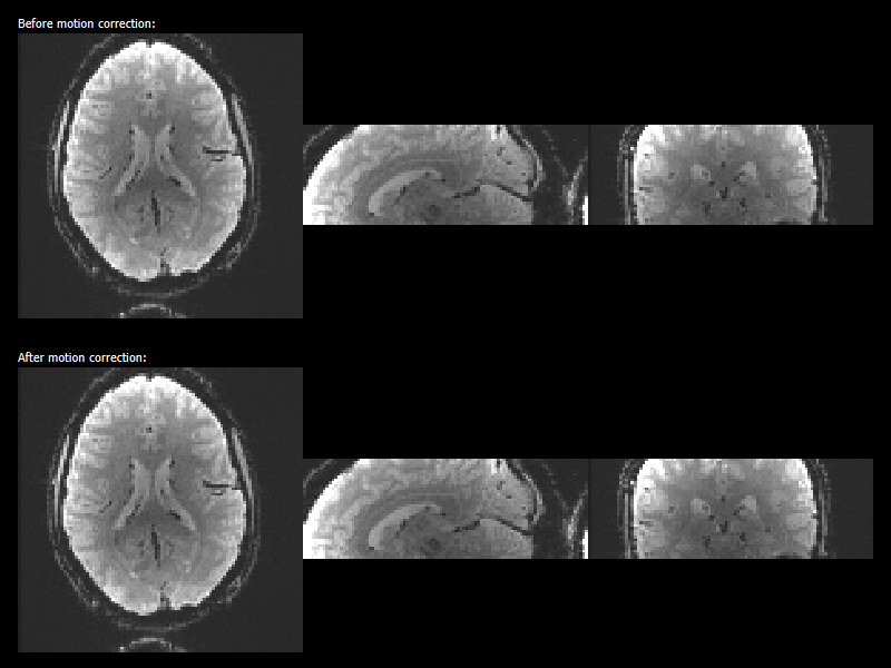
The before / after animation as well as the difference images of the last and first (reference) volume indicate that the relatively strong motion has been reduced substantially.
Copyright © 2023 Rainer Goebel. All rights reserved.