BrainVoyager v23.0
POI Path Tools
Patches-Of-Interest (POIs) usually specify regions derived from anatomically or functionally defined cortex patches such as significant clusters from a localizer experiment. The POI path tools described here provide specific functions that are useful for one-dimensional POIs acting as "lines", e.g. to mark borders between demarcated areas or for manually specified macroanatomical line landmarks or to define successive points for one-dimensional sampling of data through an active cluster. An issue with such POIs is that the order of vertices does not reflect this purpose since they are arranged as default in a rather random order (usually ordered with increasing vertex indices but these vertex index numbers have no meaning with respect to the mesh topology). The first feature of the path tools is, thus, to convert a "line" POI into a true path by reordering the vertices such that they progress from a starting vertex in an orderly fashion along neighbor vertices. To perform a true path, it must also be specified which of the two ends of the line provides the first ("seed") vertex of the path. This seed vertex can be determined by setting the reference vertex of a POI to the beginning or ending vertex of the line POI before reordering the vertices in a path.
Note. If the reference vertex is not specified as one of the two end points (or a vertex within the line), the program simply uses the first vertex index in the original line POI as the "seed" vertex; this scenario should be avoided since it will likely lead to a "path" that starts at some arbitrary point within the line moving to one end of the line and then jumping to the "free" vertex next to the seed vertex to complete the "path" in the opposite direction.
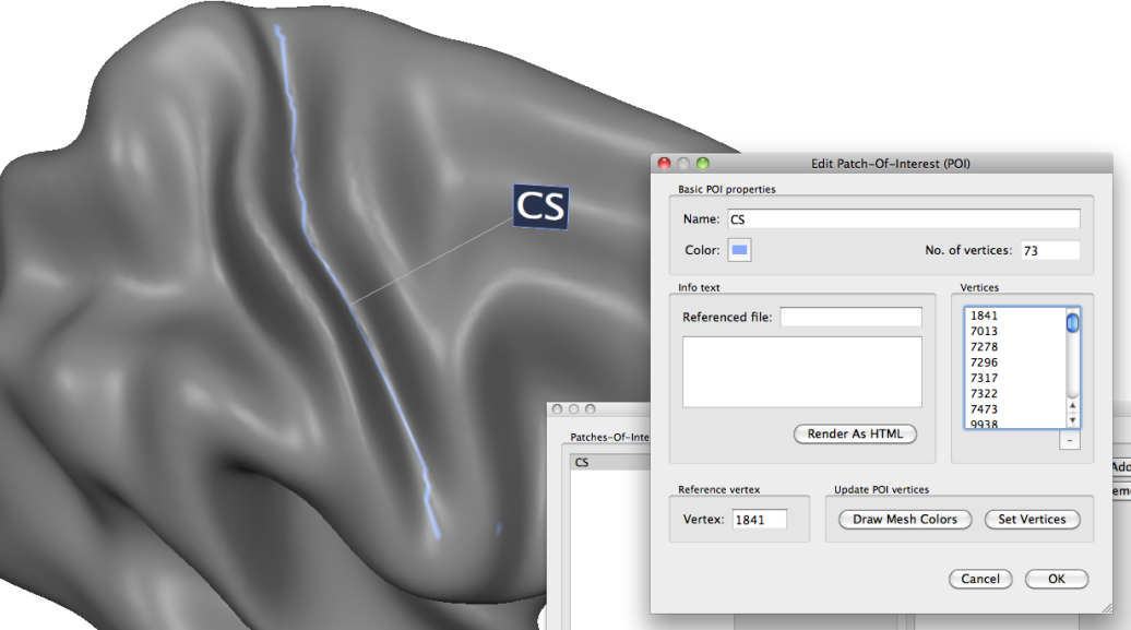
In the snapshot above a line POI has been defined along the central sulcus of a partially inflated cortex mesh by Shift-clicking a few points in the fundus of the sulcus. The No. of vertices field in the Edit Patch-Of-Interest (POI) dialog indicates that the POI consists of 73 vertices. The Vertices box shows some of the defined vertex indices that are sorted as default in ascending order. The Delete (-) button below the Vertices box allows to remove selected vertices from a POI definition. Since in this example one vertex was clicked accidentally outside the sulcus, it has been removed using this button yielding a modified POI with 72 entries. The Reference vertex entry shows that the first vertex (index 1841) has been automatically selected as the reference vertex which is located roughly in the middle of the line POI.
Creating Path POIs
In order to set the reference vertex to one of the two vertices at the end of the line POI, you can enter the index number of the vertex (if known) directly in the Vertex spin box of the Reference vertex field of the Edit Patch-Of-Interest (POI) dialog (see snapshot above). To find the index number of a vertex, you can simply Ctrl-click on a vertex. These two steps can be combined by turning on the Specify by CTRL-clicking option in the Reference vertex definition field of the POI Functions tab of the POI Analysis Options dialog. Then one can Ctrl-click (Command-click on Mac OS X) one of the respective vertices; to simplify this operation, you may zoom the mesh first; it may also help to turn on Wireframe Mesh display mode; note that the targeted vertex will be selected if it is the closest vertex with respect to the position of the mouse click; in case that a wrong vertex is selected, simply repeat the Ctrl-clicking operation until the correct vertex is highlighted.
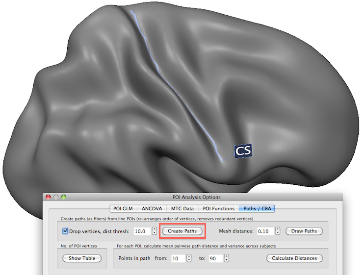
In order to convert a line POI in a true POI path, click the Create Paths button in the Paths / CBA tab of the POI Analysis Options dialog. This will convert the order of vertices in all POIs available (in this example only one POI has been defined) in an orderly fashion progressing from a seed vertex along a path to the final vertex. The Drop vertices option can be used to stop "path tracing" if the next closest vertex is further away from the current vertex than the value specified in the Dist thresh field; this is useful in paths that contain several vertices in a small region (e.g. when several clicks were performed roughly in the same spot) since this option then "skeletonizes" the path; this has an effect in case that vertices are skipped when producing a shortest ("straight") path and they will likely not visited when the end vertex of the path is reached since they are then likely too far away (i.e. further than the distance threshold). The program will report in the Log tab whether the POI could be successfully reordered as a path. The snapshot above shows that the reference vertex has been now specified as the vertex with the most inferior position of the central sulcus (CS) POI; with this seed vertex, the resulting path POI starts at the bottom vertex and progresses upward via neighboring vertices until the top most vertex at the end of the CS poi has been reached. If the Edit Patch-Of-Interest (POI) dialog is reopened for the "CS" POI, the order of vertices will look different then before indicating the re-arrangement into a true POI path.
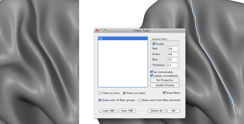
Besides the standard POI visualization that marks those mesh vertices belonging to the POI with the POI's color, calculated path POIs can also be drawn as lines above a mesh by clicking the Draw Paths button after creation of POI paths. The separation of the resulting path lines from the mesh is determined by the value in the Mesh distance text box (usually the default setting of 0.1 is fine). The snapshot above on the left shows the created line for the CS POI path. Note that this function actually creates the line representation as a "fiber" in the same way as the fibers used for visualization of DTI fiber tracts; this representation, thus, allows to apply all operations and visualization that are availabe for DTI fibers; the snapshot above on the right, for example, shows the CS path POI in the Fibers Table dialog; in order to draw the POI path as a tube (that is better visible as the line), the Fibers as tubes option has been selected and the CS POI path is redrawn as a tube (see right side above).
Analyzing Distances Between Paths
In some situations it may be helpful to quantify the distances between paths, e.g. when evaluating the effect of cortex-based alignment. How can the distance between two pahts be defined? In the approach used in BrainVoyager (modified Hausorff distance) the distance of two paths is calculated as follows. First the distance from each vertex of a path i to the vertex of path j with the shortest distance is determined; the obtained values for all vertices are then averaged to get the mean distance from path i to path j. To obtain the final distance measure the separately calculated distances from path i to path j and from path j to path i are averaged.
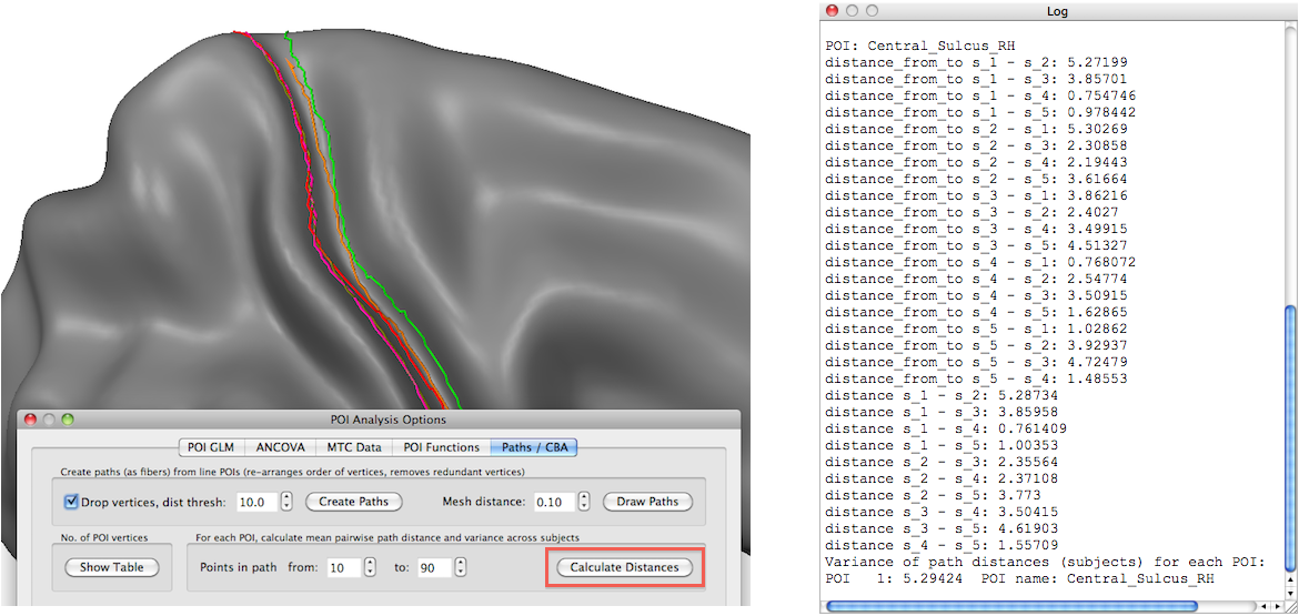
In the snapshot above, five path POIs are visualized (as tubes) in a common cortex space before running cortex-based alignment. The Hausdorf path distances can be calculated by clicking the Calculate Distances button in the Paths / CBA tab of the POI Analysis Options dialog (see red rectangle in snapshot above). The resulting distance values are printed in the Log pane (see right side in the snapshot above). The snapshot below shows the five central sulcus path POIs after cortex-based alignment. The Log pane on the right shows that the distances have been substantially decreased indicating the successful alignment of the grooves of the five sulci despite a purely curvature-based alignment procedure.
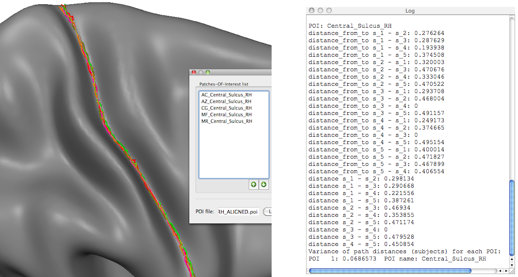
Note that besides the "directed" and averaged pairwise path distances, the reported results in the Log pane also include the "Variance of path distances for each POI" which is a good measure to summarize the pairwise path distances, e.g. across subjects.
Copyright © 2023 Rainer Goebel. All rights reserved.