BrainVoyager v23.0
Anatomical Normalization Workflow
The anatomical normalization workflow can be used to transform anatomical brains from native space into a standard space such as MNI or Talairach space. Besides the transformed output datasets, the transformation files created by this workflow can also be used to transform functional datasets of the respective subjects and sessions into normalized space.
Creating and Connecting the Workflow
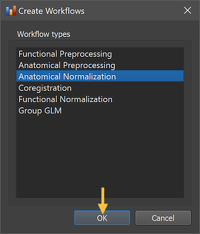
As other workflows, the anatomical normalization workflow can be created using the Create Workflows dialog that can be launched by using the Create button in the Workflows tab of the Data Analysis Manager window. In the appearing dialog, the Anatomical Normalization entry need to be selected (see screenshot below). Note that one could add other workflows at the same time but here we describe the creation of each workflow in a separate step.
After clicking the OK button, the new workflow appears in the Workflows tab (see figure below). The ID column indicates that the unique identifier '2' has been assigned to this workflow; the column Type shows the generic name "Anatomical Normalization" for the assigned (and stored) type ID (3); the column Name shows the default name "anat-normalization" that has been assigned to this workflow, which can be changed in the Workflow dialog. The empty cells in the Input and Output columns indicate that the instantiated anatomical normalization workflow is not yet ready to be executed since no data connections have been made. To connect the workflow to input data, the Connect Workflows dialog is used, which can be invoked by clicking the Connect button in the Workflows tab.
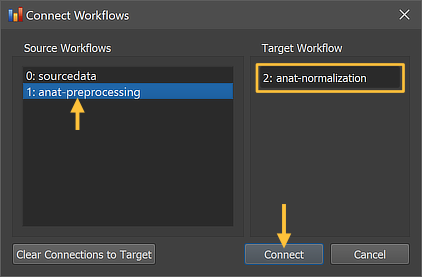
The Connect Workflows dialog shows in the Source Workflows list on the left side all available data sources including the NIfTI files in the sourcedata folder and the generated outputs of other workflows. A specific workflow is identified by its unique ID and its name ("[workflow-ID]: [workflow-name]"). On the right side the target workflow is displayed to which data can be connected which is the currently selected anatomical normalization workflow. Since usually the output of the preprocessing workflow (inhomogeneity corrected extracted brain in native space) is used as input for the normalization workflow, the "1: anat preprocessing" workflow is selected in the Source Workflows list. One could also use the original (unprocessed) datasets in the sourcedata folders but one usually wants to have both preprocessed and normalized datasets and also the spatial normalization routines work better (more robustly) when using preprocessed data as input. Note that (as with the preprocessing workflow) no specific dataset (file name) needs to be selected since the program uses the predictable BIDS directory tree to find the appropriate anatomical file (per session) in the respective "anat" folder of each subject in the preprocessing workflow.
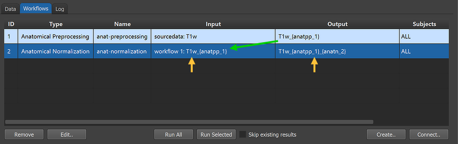
After clicking the Connect button in the Connect Workflows dialog, the established connection is made and the workflow entry is updated accordingly. The arrows in the figure above indicate that the anatomical normalization workflow will use the output of workflow 1 as input identified with the generic file name "T1w_{anatpp_1}". The program has retrieved this name by checking the respective entry "outfile" in the "workflowinfo.json" file of the input (preprocessing) workflow, which is '{sub-id}_{ses-id}_T1w_{anatpp_1}'; to use a short string in the Input column of the Workflows tab, the subject and session IDs (as well as the file extension) have been removed in the displayed name. Similarly the generated output file name 'T1w_{anatpp_1}_{anatn_2}' of the new (normalization) workflow is displayed in shortened form in the Output column. Note that he generic output name now contains two processing variables, "{anatpp_1}" and "{anatn_2}".
Inspecting and Editing Workflow Settings
In order to inspect and eventually change settings, such as parameters that control the processing, one can invoke the Workflow dialog by double-clicking the workflow entry in the Workflows table or by clicking the Edit button below the table after selecting the workflow.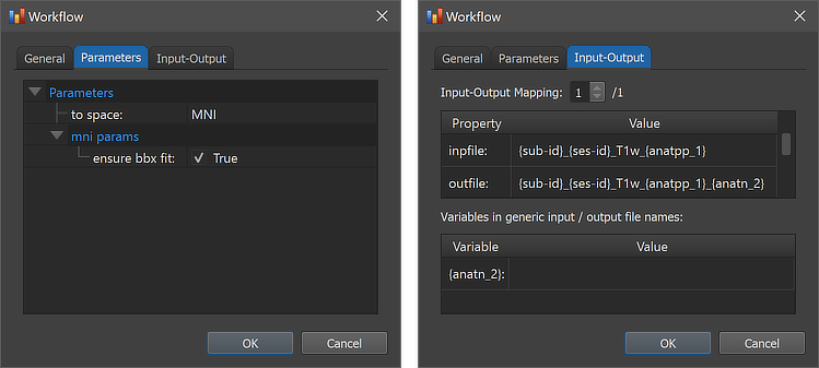
The figure above shows the contents of the Parameters tab (left) and he Input-Output tab (right) of the Workflow dialog. The Parameters tab shows the parameters specific for the selected workflow, which can be inspected as well as changed. The default preprocessing options set the to space option to 'MNI' as default (other settings are 'TAL' and 'ACPC'). For the default MNI transformation, the ensure bbx fit option (see MNI normalization topic) can be turned on (default) or off in the mni params settings section.
The right side of the figure above shows the Input-Output tab, which displays information related to the established data flow connection(s). Each connection (if more than 1) can be viewed by changing the Input-Output Mapping number. The inpfile and outfile fields show the processed T1-weighted anatomical file name with the subject and session substrings replaced by (loop) variables (enclosed by curly braces '{}'). As mentioned above, the outfile entry has an extended file name that adds the substring "_{anatn_2" ('n' for normalization) to the substring from the preprocessing workflow "_{anatpp_1}"; the processing variable "{anatn_2}" is also visible in the Variables in generic input / output file names field. When running the workflow, processing variables will be replaced with concrete values (substrings) that depend on the included processing steps and parameter settings. When inspecting the variables section in the dialog after running the workflow, the concrete values will be displayed. Note that variables (and their values if available) will be handed over to any subsequent workflow so that file names with additional substrings can be constructed before any workflow has been executed.
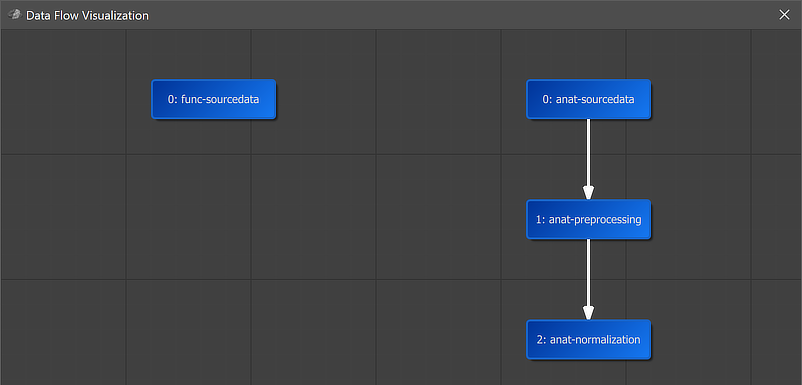
A global overview of the established connection is graphically displayed when clicking the Data Flow button in the main toolbar of the Data Analysis Manager (see screenshot above). In the appearing visualization the "2: anat-normalization" workflow is placed below the "1: anat-preprocessing" workflow, which itself is placed under the "0: anat-sourcedata" node. Arrows connecting the nodes indicate the established anatomical processing pipeline.
Running the Workflow
After selecting the workflow in the Workflows tab (single-click on its row in the table), the prepared anatomical workflow can be executed using the Run Selected button (or the Run All) button). In case that the Skip existing results option has been turned on, the program will not process datasets in case that the expected output data are already available. This option is useful (saving time) in case that one adds more subjects to a project and wants to preprocess only the newly added ones. An alternative way to restrict the workflow to specific subjects is to select the desired subset of subjects in the Subjects field in the General tab of the Workflow dialog.
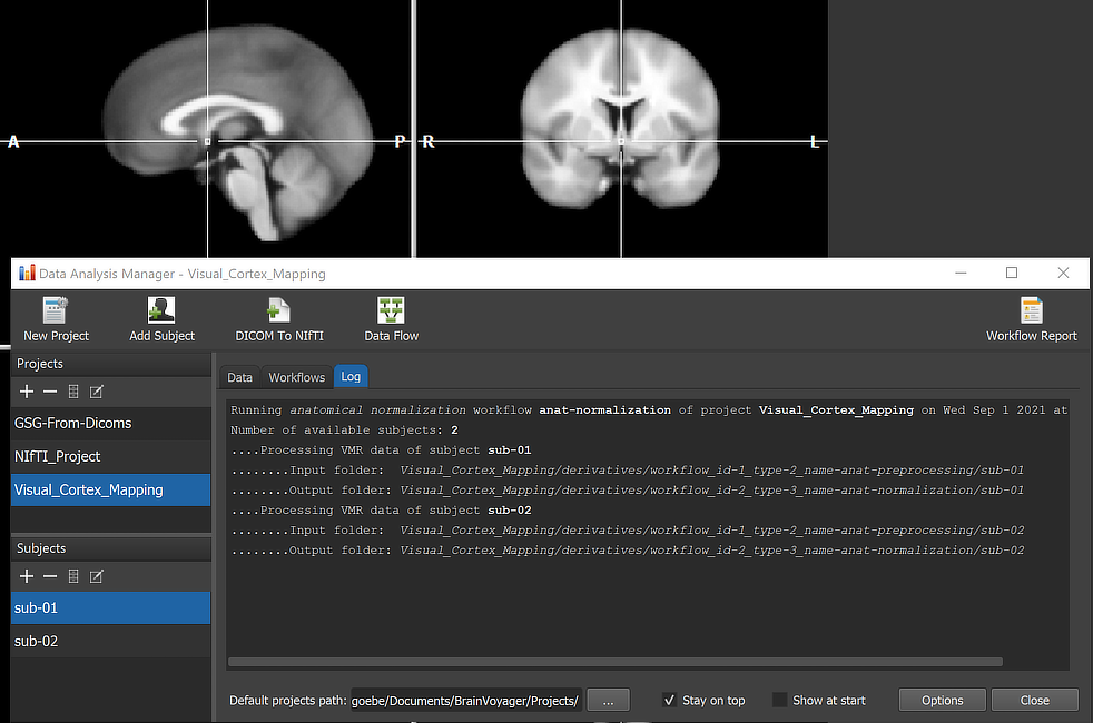
When running a workflow, the program displays the progress of data processing in the Log tab of the Data Analysis Manager window. The screenshot above captures a moment during anatomical (MNI) normalization of the dataset of subject 'sub-02'.
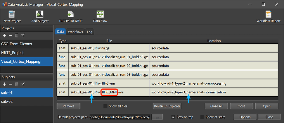
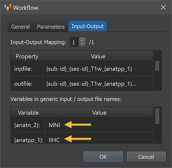
After the workflow has finished processing, the main produced data files can be inspected by switching to the Data tab of the Data Analysis Manager. The arrows in the screenshot above highlight the newly added entry for the selected subject but the same output will be available for all subjects (here only 2) in case that processing was successful. The red rectangle highlights that the produced output file name in the File column now has the substring "_IIHC_MNI" as compared to the original input file name shown in the first row of the Subject Data table. The substrings "IIHC" and "MNI" are also stored now as the values of the "{anatpp_1}" and "{anatn_2}" variables in the "workflowinfo.json" file inside the normalization workflow folder as shown in the invoked Workflow dialog (see screenshot below).
The Location column of the Data table of the Data Analysis Manager indicates that the produced files are stored inside the created workflow directoy (under the derivatives folder of the project); the name of the workflow folder 'workflow_id-2_type-3_name-anat-normalization' contains the unique workflow ID ('2'), its type ('3') and its name ('anat-normalization). Note that you can open the produced file by simply double-clicking its row in the Data table or by clicking the Open button below the table after selecting the respective table row. The location on disk of the generated file can be shown in the Finder (macOS) or Explorer (Windows) by clicking the Reveal in Finder or Reveal in Explorer button. The figure below shows the full generated directory tree of the workflow on disk.
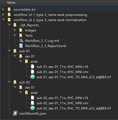
This view illustrates that the workflow organization on disk replicates the BIDS directory tree for the relevant data (here "anat" folders). The file names in the "anat" folders reveal that the normalized MNI output data are stored both in 8-bit (VMR) as well 16-bit (V16) format. Additionally a MNI transformation (.TRF) file has been stored per subject and session, which is needed when transforming functional data into normalized space. Besides the BIDS sub-directories for each subject, the "_QA_Reports_" folder is also stored inside the workflow directory containing the full log (Markdown) text file and the generated quality report as a BrainVoyager notebook (see below), which will be shown automatically when the workflow has completed. The workflow report can also be shown at a later time by clicking the Workflow Report icon in the main toolbar of the Data Analysis Manager after selecting the respective entry in the Workflows table.
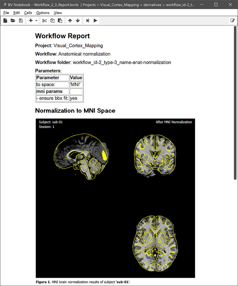
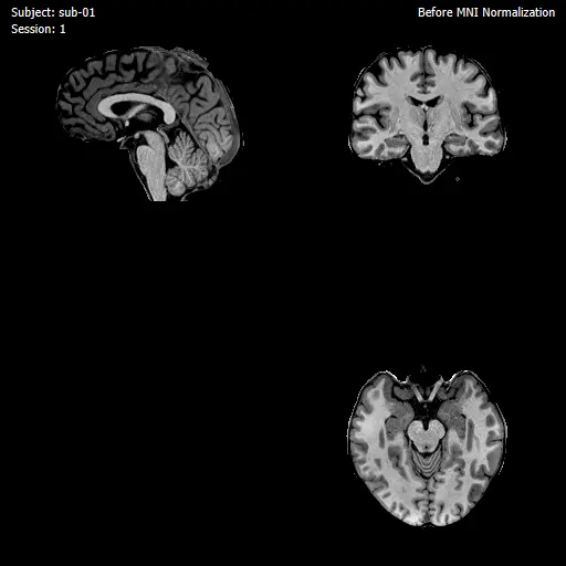
Note that the figures generated per subject are actually animations (not visible in screenshot above) showing the anatomical dataset before and after normalization. The animation embedded in the quality report for subject 'sub-01' is shown below.
Copyright © 2023 Rainer Goebel. All rights reserved.