BrainVoyager v23.0
Group GLM Analysis Workflow
After creating anatomical and functional data in normalized space, workflows can be specified and executed that perform statistical analysis of the data. The group GLM analysis workflow allows to run group-level random or fixed effects GLM analyses using the VTC files produced by a specified functional normalization workflow. Furthermore, contrasts can be defined that will be used to calculate and overlay desired statistical maps. The specified workflows simplify substantially the setup of multi-subject GLM analyses since multi-study design matrix files are build automatically.
Creating and Connecting the Workflow
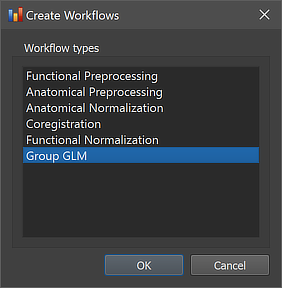
As other workflows, the group GLM analysis workflow can be created using the Create Workflows dialog that can be launched by using the Create button in the Workflows tab of the Data Analysis Manager window. In the appearing dialog, the Group GLM entry need to be selected (see screenshot below).
After clicking the OK button, the new workflow appears in the Workflows tab (see figure below). The ID column indicates that the unique identifier '6' has been assigned to this workflow; the column Type shows the generic name "Group GLM" for the assigned (and stored) type ID (6); the column Name shows the default name "group-glm" that has been assigned to this workflow, and which can be changed in the Workflow dialog. The empty cells in the Input and Output columns indicate that the instantiated group GLM workflow is not yet ready to be executed since no data connections have been made. To connect the workflow to input data, the Connect Workflows dialog is used, which can be invoked by clicking the Connect button in the Workflows tab.
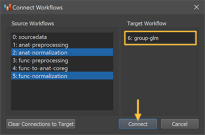
The Connect Workflows dialog shows in the Source Workflows list on the left side all available data sources including the NIfTI files in the sourcedata folder and the generated outputs of other workflows A specific workflow is identified by its unique ID and its name ("[workflow-ID]: [workflow-name]"). On the right side the target workflow is displayed to which data can be connected to, which is the currently selected group GLM workflow. Since a group GLM requires normalized functional data as input, the "5: func normalization" workflow is selected as input for the group-level statistical analysis. While this selection would be sufficient, the "2: anat normalization" workflow has been selected as a second source since this allows to overlay statistical maps not only on a template brain but also on averaged or individual brains from the analyzed group of subjects.

After clicking the Connect button in the Connect Workflows dialog, the established connections are made and the workflow entry in the Workflows table of the Data Analysis Manager is updated accordingly. The green arrow in the figure above indicates that the group GLM analysis workflow will use the output (VTC files) of the functional normalization workflow (ID: 5) as input; the additionally specified anatomical normalization source is not shown here but can be inspected in the Workflow dialog (see below). The generated output file name in the Output column '{glm-type_6}_ses-01_task-vislocalizer_{gglm_6}' is based on the name of the functional data that is extended with a leading substring '{glm-type_6}_' and a trailing substring '_{gglm_6}'; the two processing variables in these substrings will be replaced with appropriate names when running the workflow depending on parameter settings (see below).
Inspecting and Editing Workflow Settings
In order to inspect and eventually change settings, such as parameters that control the processing, one can invoke the Workflow dialog by double-clicking the workflow entry in the Workflows table or by clicking the Edit button below the table after selecting the workflow.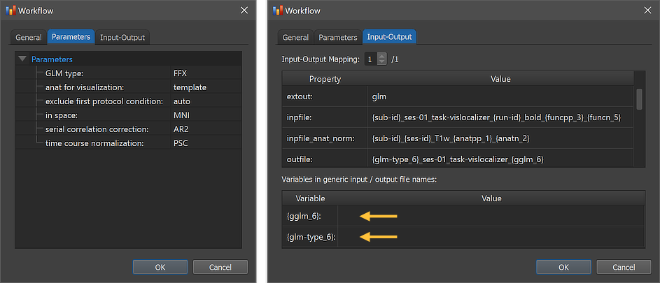
The figure above shows the contents of the Parameters tab (left) and he Input-Output tab (right) of the Workflow dialog. The Parameters tab shows the parameters specific for the selected workflow, which can be inspected as well as changed. The GLM type parameter has been set as default to "FFX" as default specifying to run a fixed-effects GLM analysis. If enough subjects are included (in the example only 2 subjects are available), the parameter can be changed to the "RFX" string to run a random-effects analysis. A third value "FFX_sep_preds" can be used to run a fixed-effects analysis but with separate predictors for each subject. The anat for visualization parameter is set to "template" as default, which will visualize calculated contrast maps on the default (here: MNI) template brain. Since also a normalized anatomical source was specified, this parameter can also be set to "average" to visualize statistical maps on the group average brain, which will be calculated by the workflow using the normalized anatomical datasets of all included subjects. The in space parameter must match the normalized functional and anatomical data specified as input (here: MNI). The serial correlation correction parameter is set to 'AR2' as default; it can also be set to "AR1" or "None" (or empty string). The time course normalization parameter is set to 'PSC' (percent signal change transformation) as default; it can also be set to "z" (z transformation) or "None" (or empty string). The exclude first protocol condition parameter is set to 'auto' as default, which will check whether the name of the first condition of provided protocols is "Rest", "Fixation" or "Baseline". If so, the first condition is excluded when creating predictor time courses for the GLM design matrix; in case of any other name, the first condition will be included and a condition predictor will be created. If one knows that the first condition is a baseline condition (independent of its name), one can set the value of this parameter to 'yes'; similarly if one knows that no baseline condition is explicitly defined, one can set this parameter to 'no'.
The right side of the figure above shows the Input-Output tab, which displays information related to the established data flow connection(s). Each connection (if more than 1) can be viewed by changing the Input-Output Mapping number. The inpfile and outfile fields show the generic name of the functional files with the subject and session substrings replaced by (loop) variables (enclosed by curly braces '{}', e.g. '{sub-id}'). As mentioned above, the outfile entry specifies the file name of the calculated group GLM containing the two processing variables '{glm-type_6}' and '{gglm_6}', which are also visible in the Variables in generic input / output file names field (see arrows). When running the workflow, these and other processing variables will be replaced with concrete values (substrings) that depend on the included processing steps and parameter settings of the respective workflows. When inspecting the variables section in the dialog after running the workflow, the concrete values of all processing variables will be displayed. Note that the generic name of the output of the specified anatomical normalization workflow is also shown in the inpfile_anat_norm entry.
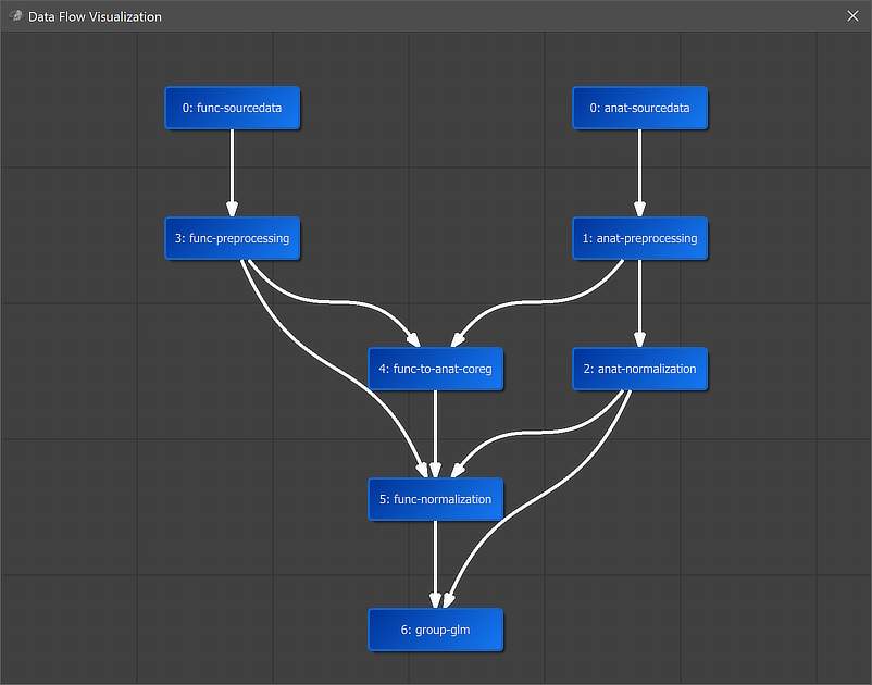
A global overview of the established connection is graphically displayed when clicking the Data Flow button in the main toolbar of the Data Analysis Manager (see screenshot above). In the appearing visualization the "6: group-glm" workflow is placed below the "5: func-normalization" workflow, which provides the main input data. Since an anatomical input was also specified, the "2: anat-normalization" workflow is also connected to the group GLM workflow. It is also placed in the middle of anatomical and functional data since it uses both types of data as input. The arrows connecting the nodes indicate the established anatomical and functional processing pipeline.
Running the Workflow
After selecting the workflow in the Workflows tab (single-click on its row in the table), the prepared functional normalization workflow can be executed using the Run Selected button (or the Run All) button). In case that the Skip existing results option has been turned on, the program will not process datasets in case that the expected output data are already available. This option is useful (saving time) in case that one adds more subjects to a project and wants to preprocess only the newly added ones. An alternative way to restrict the workflow to specific subjects is to select the desired subset of subjects in the Subjects field in the General tab of the Workflow dialog.
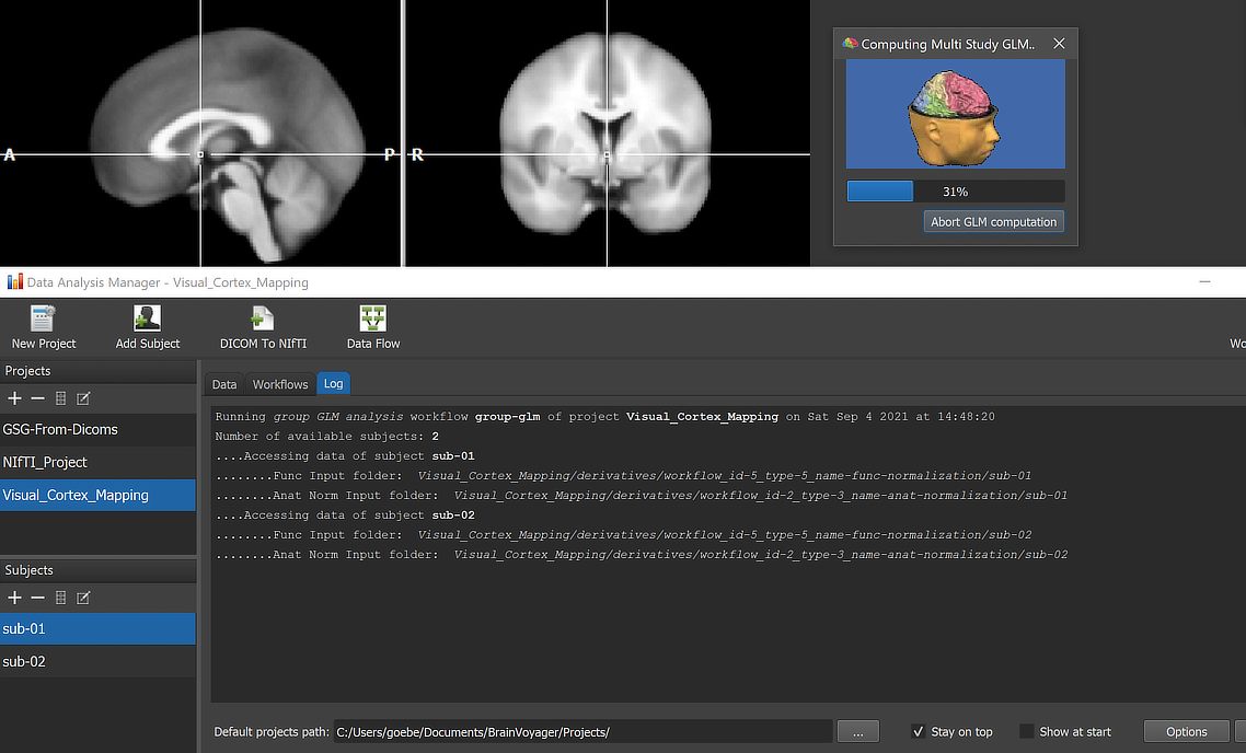
When running a workflow, the program displays the progress of data processing in the Log tab of the Data Analysis Manager window. The screenshot above captures a moment during GLM calculation.
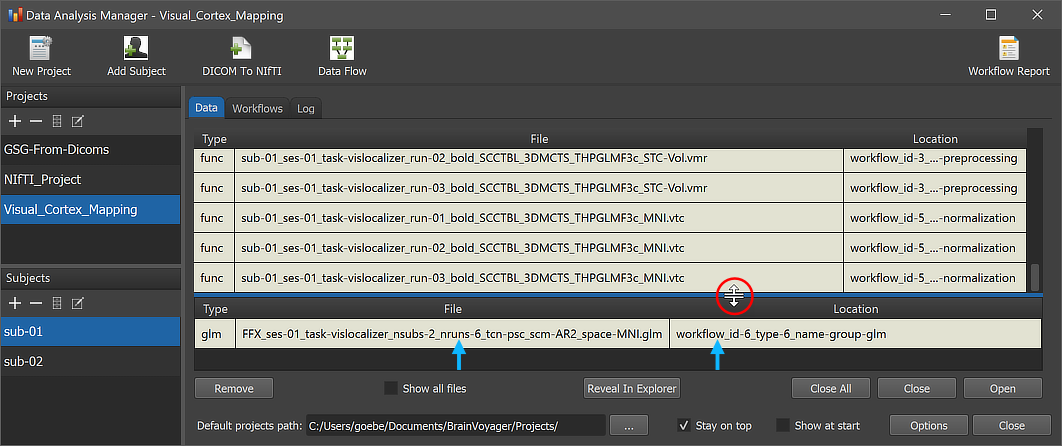
After the workflow has finished processing, the produced .GLM file can be inspected by switching to the Data tab of the Data Analysis Manager. The arrows in the screenshot above highlight the newly added entry. Note that the file is added to the Group Data table, which is placed below the Subject Data table. The splitter (see red circle) can be used to change the relative size of the subject vs group data panes; the splitter appears when hovering with the mouse over the line separating the two panes. The Location column of the Group Data table of the Data Analysis Manager indicates that the GLM file is stored inside the created workflow directoy (under the derivatives folder of the project); the name of the workflow folder 'workflow_id-6_type-6_name-group-glm' contains the unique workflow ID ('6'), its type ('6') and its name ('group-glm'). Note that you can load the .GLM file to the currently open anatomical file (which should be in the same normalized space) by simply double-clicking its row in the Group Data table or by clicking the Open button below the table after selecting the respective table row. The GLM file will be loaded and an omnibus contrast (all predictors of interest set to '1') will be shown; futhermore the Overlay GLM dialog will be launched allowing to define more specific contrasts.
Processing variables and their values are now also stored in the "workflowinfo.json" file inside the functional normalization workflow folder that has been updated when running the workflow. The variables can be inspected by opening the Workflow dialog (see screenshot below).
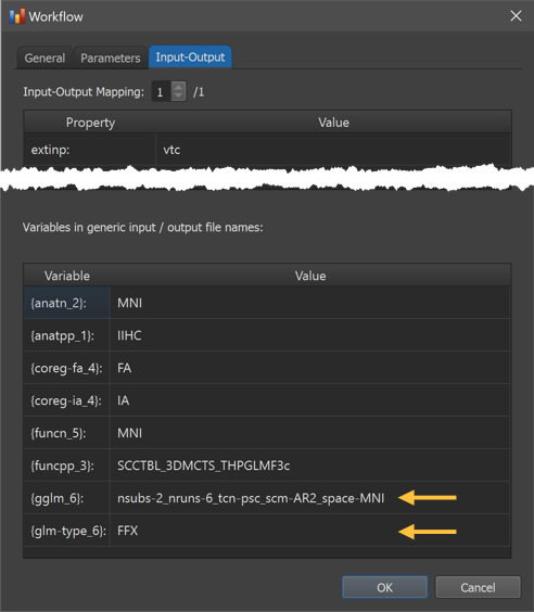
The Variables in generic input / output file names table now shows the values for the '{glm-type_6}' and '{gglm_6}' variables of the group GLM workflow (see arrows above) as well as the values of all other processing variables appearing in the generic input and output file names in the Input-Output Mapping table (not shown here but see earlier screenshot).
The location of the generated GLM file on disk can be shown in the Finder (macOS) or Explorer (Windows) by clicking the Reveal in Finder or Reveal in Explorer button after selecting the GLM file in the Group Data table. The figure below shows the full generated directory tree of the workflow on disk.
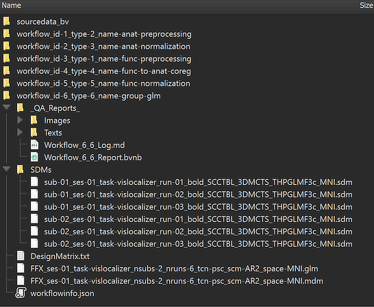
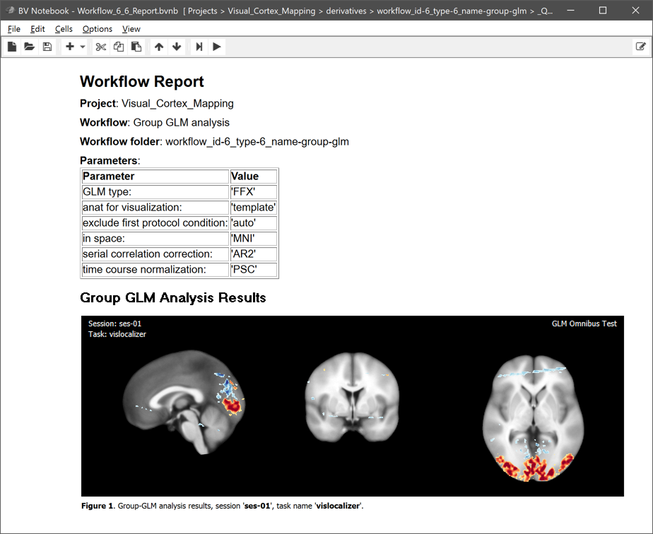
The main output, the calculated .GLM file, is placed directly under the workflow folder. This is different to the preprocessing workflows since the analysis runs across all subjects making subject-specific BIDS directory trees unnecessary. The name of the .GLM file contains substrings that identify parameters and other important information, As expected, the GLM name starts with the string "FFX" since we requested a fixed-effects GLM. The GLM has used the data from session 'ses-01' (the only session in this example) for all runs with the task name "vislocalizer". The 'nsubs-2' substring sepcifies the number of subjects (2) and the 'nruns-6' string the total number of runs (2 x 3). The 'tcn-psc' string (tcn = time-course normalization) tells us that each voxel time course was percent-signal change transformed before fitting the GLM. The 'scm-AR2' string (scm = serial correlation model) indicates that an AR2 model was used to correct for serial correlations. The 'space-MNI' string finally tells us that the GLM was calculated with data in MNI space. Next to the .GLM file also the automatically generated multi-subject design matrix (.MDM) file is stored, which is needed to run the GLM procedure. The .MDM file lists the full paths to the .VTC files in the functional normalization directory as well as the corresponding single-run design matrix (.SDM) files that were calculated from the protocols and stored in the "SDMs" folder inside the group GLM workflow directory. The "_QA_Reports_" folder is also stored inside the workflow directory containing the full log (Markdown) text file and the generated quality report as a BrainVoyager notebook (see below), which will be shown automatically when the workflow has completed. The workflow report can also be shown at a later time by clicking the Workflow Report icon in the main toolbar of the Data Analysis Manager after selecting the respective entry in the Workflows table.
Copyright © 2023 Rainer Goebel. All rights reserved.